RE-DEFINING CIRCUIT MONITORING

MCMS technology from Anord Mardix simplifies installation and connectivity while providing instant access to data in a user-friendly format. The versatile Core Module™ system is a single monitoring solution with peripherals that are optimised for branch circuit and multi-circuit monitoring applications.

KEY FEATURES

  • The versatile Core Module ™ system – a single monitoring solution with peripherals optimized for branch circuit and multi-circuit monitoring applications, designed to reduce the cost and complexity associated with legacy systems.
  • Presence of voltage detection – detects circuit breaker status even under no load conditions using a proprietary voltage field detection system. It identifies failed circuits that may go unnoticed on conventional monitoring systems.
  • Predictive circuit health analysis – uses proprietary algorithms to analyse circuit signatures over time and detect changes indicative of common failure modes in power supplies and other critical loads.
  • Waveform capture – high resolution power quality data from all circuits is stored for any power quality deviation, providing invaluable data for evaluation of power disturbances.
  • True circuit display – allows data to be expressed according to the actual panel board configuration.

MONITORING BENEFITS

RAPID INSTALLATION

    • Optimized for new and retrofit installations with no disruption to critical loads
    • Monitors up to 96 circuits
    • Options for solid core, split core CTs, Rogowski coils, and analog, discrete and pulse inputs

EASILY ACCESSED DATA

    • On-board web server provides immediate access to real-time and logged data
    • Integrated data logging supports up to 64GB storage; remotely accessible or manually exportable
    • Available cloud monitoring service
    • Customizable alarming features

EASY CONNECTIVITY

    • Select from multiple connectivity options including Modbus TCP/IP, RTU, BACnet, WiFi and cellular
    • Open protocols allow connection with any third-party monitoring system

INTELLIGENT FEATURES

    • Presence of voltage detection accurately indicates breaker status even under no load conditions
    • Predictive Circuit Health Algorithm (patent pending) detects changes in circuit performance to predict potential failures
    • True-Circuit Display mapping function presents data according to actual circuit configurations
    • Detailed power and energy monitoring per circuit including Waveform capture and THD

HIGH ACCURACY

    • True 0.5% accuracy suitable for billing applications

FIND OUT MORE

Find our further details on our Modular Ciruit Monitoring System specification, technical features and installations below.

FIND OUT MORE

DOWNLOAD OUR MCMS BROCHURE


INPUT

Input power (standard) 90-277 VAC (480 VAC 4W+G) 50/ 60 Hz
Input power (enhanced) 480-600 VAC (3W or 4W+G) 50/ 60 Hz
Voltage connection terminals 22 – 14mm/sq.
Overload protection Internally fused
Power consumption <5W / 0.1 A @ 240 VAC Channels / circuit capacity 24 x 4 channels (96 circuits total) PERFORMANCE Accuracy 0.50% Sampling rate > 3 kHz

COMMUNICATIONS

Data protocols Modbus TCP/IP (Ethernet), Modbus RTU (RS-485 2 wire), HTML (web server), SNMP and BACnet.
Modbus serial specifications 9600, 19200, 38400 Baud (selectable)
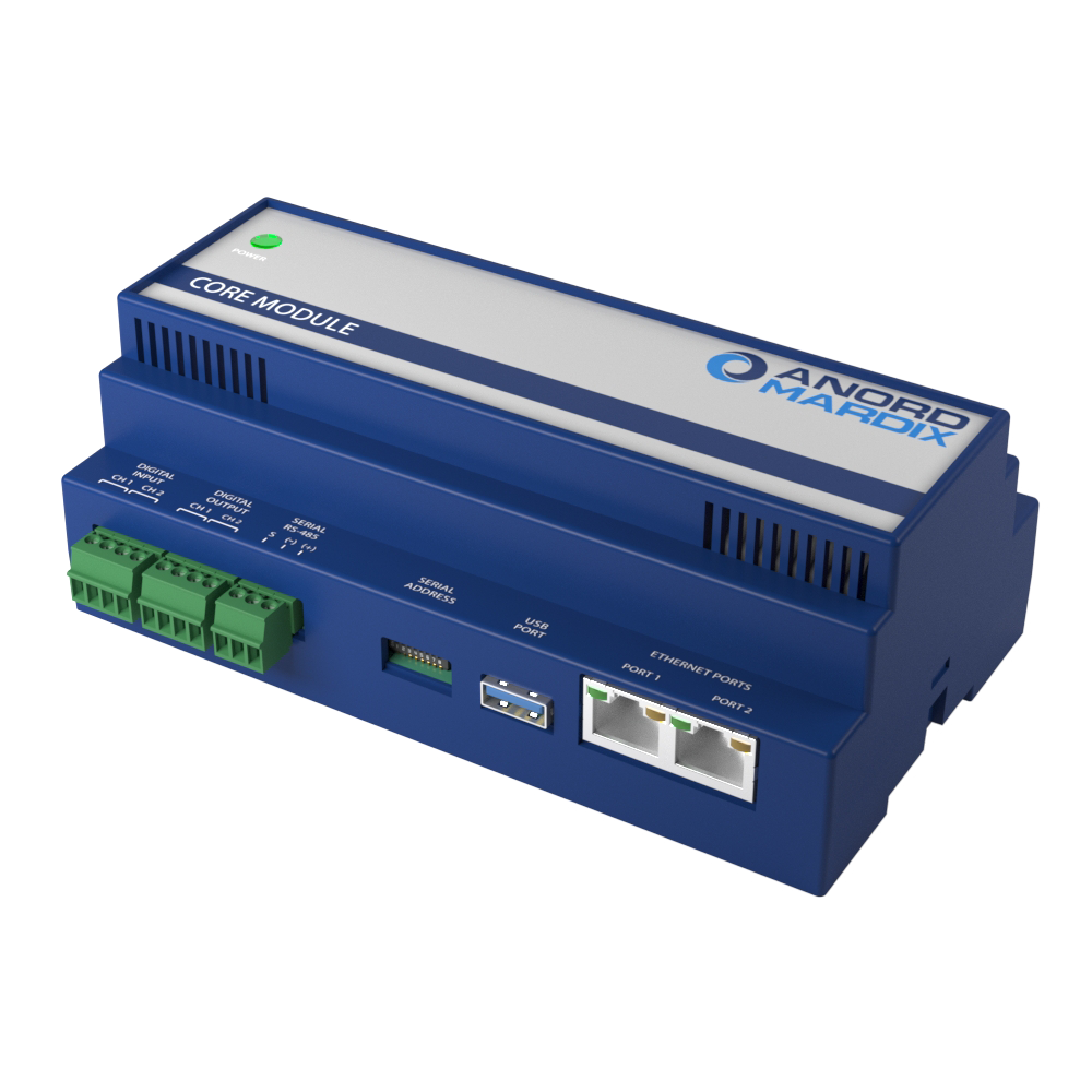
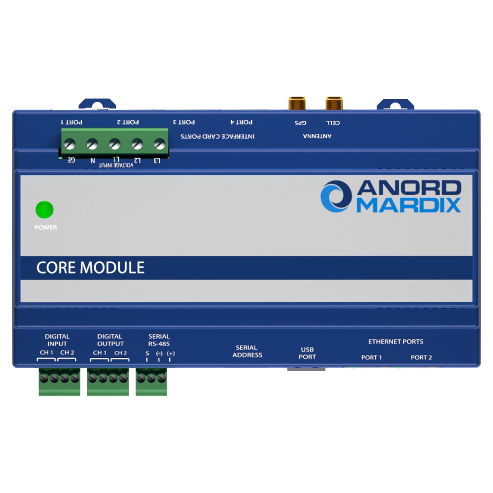
Ethernet ports 2 x RJ-45 10/100 Mbit
USB port USB 2.0 Type A
Web server HTML via standard browser
WiFi option 802.11 g/n ; requires WiFi option

ENVIRONMENTAL

Operating temperature 0 to 60 °C (32 to 140 °F) (<95% RH non-condensing)
Storage temperature -40 to 70 °C (-40 to 158 °F)
Enclosure versions NEMA 1/IP20 (indoor use); NEMA 4 / IP67 (outdoor use)

APPROVALS

Agency approvals UL Listed to EN61010-1, Cat. III, pollution degree 2, CE

CORE MODULE™ SYSTEM

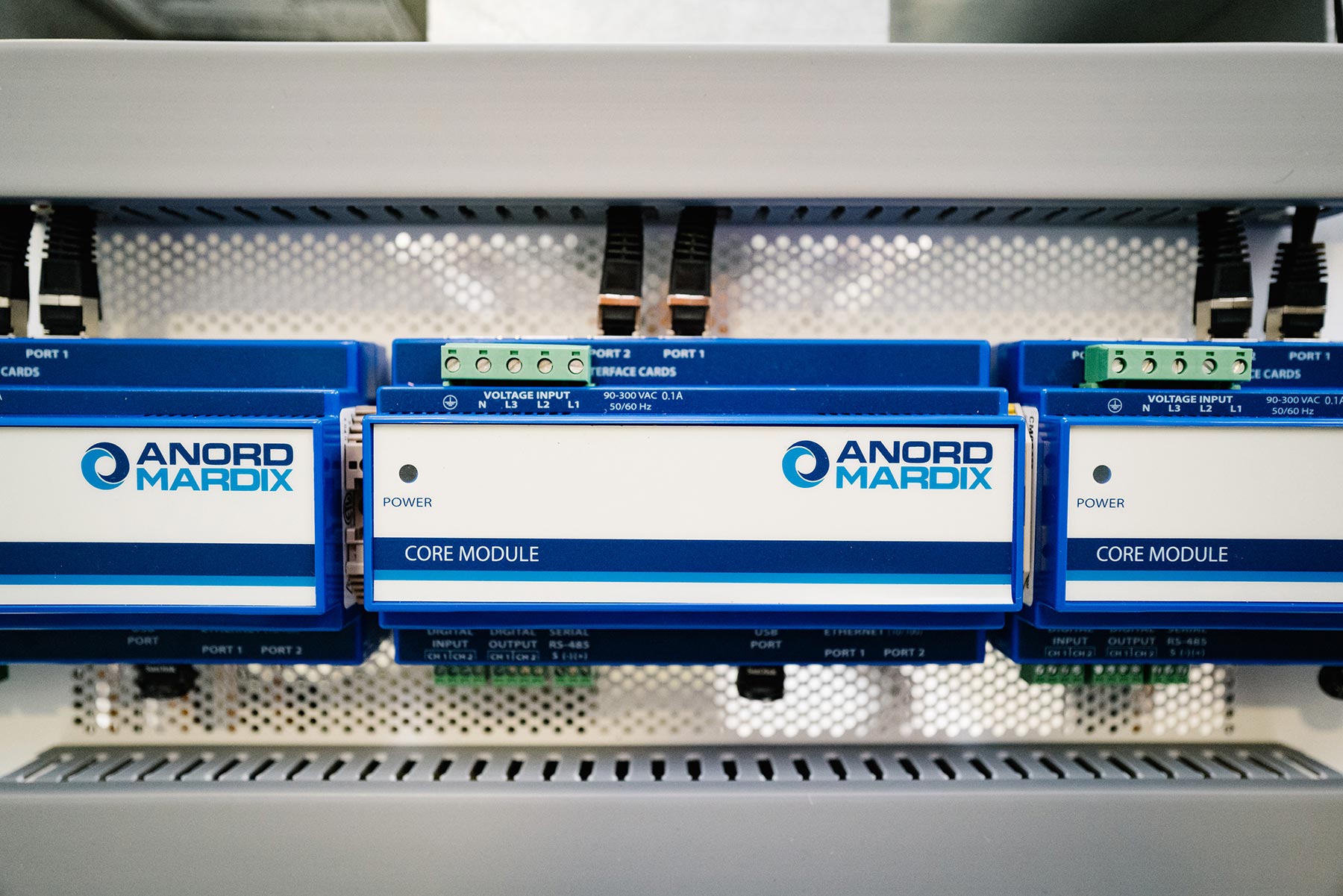
The versatile and compact Core Module™ functions as a gateway that can host up to four interface modules monitoring a total of 96 circuits. Interface modules connect via ethernet cables and are available for new and retrofit branch circuit and multi-circuit applications. Further accessories are available to enable monitoring of direct current voltages at the final circuit level

INTERFACE MODULES

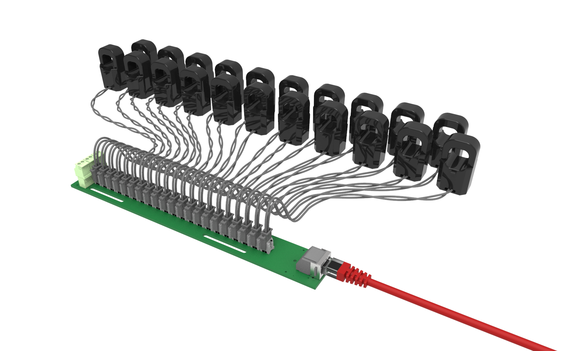
Purpose built, application-specific Interface Boards simplify installation using intuitive form factors and simplified connectivity via Ethernet cable.

  • Solid Core Panelboard CT Strip
  • Retrofit Panelboard CT Strip
  • Multi-Circuit CT Board
  • Busway Module (new installations)
  • Busway Module (retrofit installations)
  • Digital Input Card
  • Legacy Panel Retrofit Interface Board

SOLID CORE PANEL CT STRIP:

  • Used for new installations on panelboard branch circuit monitoring
  • Up to 21 circuits per strip + 3 auxiliary CT inputs (96 total)**
  • 75” and 18mm C-C versions
  • 10mm CT window w/ 100 A range
  • Optional presence of voltage sensing for breaker status per circuit

SPLIT CORE PANELBOARD MODULE:

  • Used for retrofitting installations on panelboard branch circuit monitoring
  • Floating CT interface strip with quick connect 10mm split core CTs sits on top of existing conductors
  • 24 circuits per module (96 Total)
  • Optional presence of voltage sensing for breaker status per circuit

MULTI-CIRCUIT CT MODULE:

  • 24 CTs / circuits per module (96 Total)
  • Supports 0.33 V solid core and split core CTs as well as available native Rogowski coil version available
  • Optional presence of v or breaker status per circuit

PANELBOARD MONITORING MODULE – NEW INSTALLATIONS

  • Used for new installations on panelboard branch circuit monitoring
  • Up to 21 circuits + 3 auxiliary CT inputs per strip (96 circuits or 2 x panels per Core Module)
  • 75”, 18mm and 1” C-C versions
  • 8mm CT window w/ 100 A range
  • Optional presence of voltage sensing for detects breaker status per circuit
  • Ultra-precision CTs deliver 0.5% system level accuracy
  • Virtual panel summary accurately display total panel data without the need for mains CTs

PANELBOARD MONITORING MODULE – RETROFIT INSTALLATIONS

  • The fastest and most cost-effective way to add branch circuit monitoring to existing panels
  • “Floating” CT interface strip with quick connect 10mm split core CTs locates in any raceway
  • Self-correcting CT orientation algorithm avoids installation errors
  • 24 circuit per strip including 3 auxiliary CT connections that be used for branch or mains monitoring
  • Compatible with any size CT
  • True Meter function allows for grouping of circuits to present breaker total and phase data
  • Virtual Meter function allows for summing specified circuits to provide system level total readings

BUSWAY MONITORING MODULE – NEW INSTALLATIONS

  • Used for new installations on busway tap-off monitoring
  • Each module monitors 3 or 6 circuits; up to 96 circuits per Core Module using any combination of 3 or 6 circuit monitors
  • 8mm CT window w/ 100 A range
  • Optional presence of voltage sensing for detects breaker status per circuit
  • Ultra-precision CTs deliver 0.5% system level accuracy
  • Virtual bus summary accurately displays total bus data without the need for end feed monitoring
  • Intuitive configuration with auto detection simplifies setup and allows easy allocation of phases , breaker types and circuit friendly names
  • Smart auto reporting features identifies relative location and name of each tap-offs and auto updates when tap-offs are added or removed
  • Provides waveform capture per circuit in the event of any disturbance

BUSWAY MONITORING MODULE – RETROFIT INSTALLATIONS

  • The quickest and most cost-effective way to add monitoring to existing tap-offs and end feeds.
  • Compact enclosure uses easy single hole mounting system with no voltage connections needed for installation in minutes
  • Each module monitors 3 or 6 circuits; up to 96 circuits per Core Module using any combination of 3 or 6 circuit monitors
  • Accommodates any 0.33V split core or solid core CT
  • Virtual bus summary accurately displays total bus data without the need for end feed monitoring
  • Intuitive configuration with auto detection simplifies setup and allows easy allocation of phases , breaker types and circuit friendly names
  • Smart auto reporting features identifies relative location and name of each tap-offs and auto updates when tap-offs are added or removed
  • Provides waveform capture per circuit in the event of any disturbance

REQUIRE MORE INFORMATION?

Contact us to discuss your project, or you can view more documentation and our MCMS datasheets.

  • Core Module Datasheet
  • Solid Core Panelboard Branch Circuit Monitoring Datasheet
  • Retrofit Panelboard Branch Circuit Monitoring Datasheet
  • Digital Input Card Datasheet
  • Busway Monitoring Datasheet
  • Legacy Branch Circuit Monitoring Retrofit Datasheet

MCMS Documentation

This is a message pop up

This is a message popup that can be used on the site to say something or to do a newsletter signup or somethign similar